High frequency magnetics
Revision: January 11, 2015
1. Core materials
This section discusses the characteristics of various materials used to make inductor and transformer cores. Manufacturers are encouraged to provide their catalogs and data sheets to be included. Manufacturers who are PSMA members may have a promotional block placed in this report.
A good over-view of the various magnetic materials and their selection criteria can be found in “Magnetic Core Materials in HF Applications.”1
1.1. Ferrite
1.2. Low temperature cured ferrites
1.3. Powdered metal
Powdered metal-based cores are made from small particles of magnetic material that are insulated, mixed with a binder and pressed into a solid core shape. The defining characteristic of powder cores is their low starting permeability ranging from 4 to 550 and soft-saturation characteristic. Unlike a gapped high permeability material, a powder material will gradually lose its permeability with increasing magnetization force. Coupled with powder materials with high saturation flux density, these materials can store higher amounts of energy per unit volume than ferrite.
Core loss is generally higher for powder materials than ferrite.There are three broad subtypes of powder metal cores depending on the base raw material used: iron, carbonyl iron and alloy.
1.3.1 Powder iron cores are made from reduced iron. The main advantage of powder iron is the materials high saturation flux density, high amplitude permeability, high damping and low cost. The main disadvantage of powder iron is its high core loss compared to other materials, making it more suitable for low frequency power conversion, line reactor or EMI filtering applications
1.3.2 Carbonyl iron-based cores feature low eddy current losses due its unique magnetic particle structure. This gives these types of materials a stable permeability over a wide frequency range. The main application for carbonyl iron-based cores is in high Q resonant inductors and broadband transformers at frequencies above 1MHz.
1.3.3 Alloy powder cores feature lower hysteresis losses than powder iron cores. The stability of these materials’ permeability versus magnetization force is also significantly better. Alloy powder cores excel in DC inductors in filtering and power conversion applications. There is a large variety of alloy cores including but not limited to: Sendust, Permalloy, Mollypermalloy and Silicon Steel.
1.4. Nanocrystalline and amorphous metals
1.5. Composite cores
1.6. Tape-wound cores
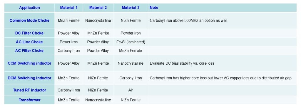
1.7. Selection criteria
The defining selection criteria for magnetic materials are: core loss, saturation flux density, inductance stability, temperature range and mechanical ruggedness.
For AC applications like high Q resonant inductors or transformers low core loss at the intended switching frequency is the primary concern. The performance factor of different material grades can be used to identify the material with the lowest core loss at a certain frequency.
For DC switching inductors, like PFC inductors, a mixture of inductance stability and core loss is desirable. For EMI filter inductors, high damping is beneficial to limit parasitic resonances in the filter. In addition, a high impedance over the desired filtering frequency range is crucial. For DC filter inductors, a high DC bias stability is desired. The material saturation constant can be used to evaluate different materials in this regard. For AC line filter inductors, a high saturation flux density and high amplitude permeability are beneficial.
1Magnetic Core Materials in HF Applications; Dr. Jonas Mühlethaler, Gecko-Simulations, AG; an APEC2014 Industry Session
2. Core geometry and scaling
This section is not to provide a compendium of the many stock magnetic core shapes available; that information is in the “Fabrication technology” section, and also may be found in various vendor catalogs under “Core materials.”
Most vendor catalogs give material characteristics using data taken with a “standard core,” though the “standard core” is anything but standard, varying widely from vendor to vendor, and many catalogs provide no information about what “standard core” is used for their data. This section provides a caution that the characteristics of other shapes and sizes may be quite different.
Information on the effect of size and geometry on core characteristics is sparse and largely qualitative. An objective is to gather more information and to develop more rigorous predictive tools. Of particular interest is scaling a core for higher frequency. Some information on scaling can be found in “Demands for High-efficiency Magnetics in GaN Power Electronics.”1
Dan Jitaru gave a presentation on “Frequency, Where We are Today, and Where We Need to Go.”2 It contains a lot of information on making transformers for high frequency applications, including methods for reducing losses due to fringing.
2.1. Solid cores
2.1.1. Matrix transformers
In a matrix transformer (later called “flat transformers), a number of small cores replace a large core. There are some data suggesting that a string of small cores may have substantially lower core loss than an equivalent single core of comparable volume. The data set is small, so this is somewhat speculative. See “Power comparison – String of beads equivalent cores.”3
2.2. Gapped cores
2.3. Distributed gap cores.
2.4. Machining special core shapes
2.5. Air core
1Demands for High-efficiency Magnetics in GaN Power Electronics, YeFeng Wo, Transform, Inc., an Industry Session at APEC2014
2Frequency, Where We are Today, and Where We Need to Go, Dan Jitaru, Rompower, Inc, an Industry Session at APEC 2014
3Power comparison – String of beads equivalent cores, Edward Herbert, Co-Chairman, PSMA Magnetics Committee, revised for this forum
3. Transformers
Transformers are widely used to provide isolation and/or voltage and current scaling.
3.1. Switch-mode power
3.1.1. Forward
3.1.2. Flyback
3.1.3. Full bridge
3.1.4. Half bridge
3.1.5. Dual active bridge (DAB)
3.2. Current sense
3.2.1. Current transformers
3.2.2. “DC” current transformer circuit
3.2.3. Rogowski coils: Rogowski coils are not truly “transformers,” but they are included here because they are replacing current transformers in many applications.
3.3. Auto-transformers
3.4. Variable transformers
3.5. Gate drive transformers
3.6. Signal transformers
3.7. Radio frequency transformers
3.8. Cruciform (constant current) transformers
3.8.1. Constant voltage transformer, ferro-resonant?
3.9. Utility-scale transformers
3.9.1. Piezoelectric transformers
3.9.1. Switched capacitors as transformers
4. Inductors
Inductors are a large group of components often used for filtering or for energy storage in power converters. Sometimes the distinction between transformers and inductors is not clear, for example: coupled inductors and fly-back transformers.
4.1. Ungapped inductors
4.2. Gapped inductors
4.2.1. Fixed gap inductors
4.2.2. Multiple-gap inductors
4.2.3. Variable-gap inductors
4.2.3.1. Step- or tapered-gap inductors
4.2.3.2. Adjustable gap inductors
4.3. Single winding inductors
4.4. Coupled inductors
4.4.1. Non-isolated
4.4.2. Isolated
4.5. Symmetrical inductors
4.6. Differential mode filter
4.7. Common mode filter
4.8. Composite Core Inductors
4.9. Inductors with Permanent Magnet Bias
5. Lossy suppressors
Inductance is a complex parameter, and at very high frequencies, the real component of inductance tends to fall off substantially, while the imaginary component of inductance dominates. Because the imaginary component of inductance is lossy (resistive), some applications exploit this characteristic to damp noise.
5.1. Ferrite beads
5.2. Lossy shielding
6. Magnetic circuits with saturating cores
Most uses of magnetic cores take great care to ensure that the cores do not saturate. There are applications, however, that exploit saturation, either for the resulting large change in impedance or for timing, or both.
6.1. Magnetic amplifiers
6.2. Royer oscillator
6.3. Beads
6.4. Core memory
6.5. Miscellaneous
7. Combination magnetic structures
There are many examples of magnetic devices consisting of more than one transformer or inductor. By combining multiple functions on a single magnetic core structure, the size may be reduced, the circuit may benefit from inherent coupling or parasitic inductance may be exploited usefully.
7.1. Three phase transformers
7.2. Integrated magnetics: A magnetic structure combining two or more magnetic elements, for example a transformer and an inductor.
7.2.1. Dual Active Bridge (DAB) integrated magnetics
7.2.2. LLC circuits
7.2.3. Cuk converter
7.2.4. Ferro-resonant voltage regulators
8. “Solid state” transformers
“Solid state” transformers is the term used by utilities for a higher frequency transformer circuit with a converter circuit on input and another on its output so that it accepts a line frequency input and has a line frequency output. Often a dc link is used, in which case the input frequency and phase are independent of the output frequency and phase.
See “Magnetics for Solid State Transformers.”1
1 "Solid State" transformers for the Smart Grid; Dr. Subhashish Bhattacharya, Dept. of Electrical and Computer Engineering, North Carolina State University, an APEC2014 Industry Session.
9. Windings
A good overview of winding for high frequency can be found in “Windings for High Frequency.”1
9.1. High frequency effects
9.1.1. Skin depth
9.1.2. Proximity effect
9.1.3. Litz wire
9.2. Resonance
9.2.1. |z| & θ vs frequency due to lc
9.3. Shielding
9.3.1. Electrostatic
9.3.2. Electromagnetic
9.3.2.1. Dissipative shields
9.3.2.2. Absorptive shields
9.4. Fringing fields due to location relative to discrete air gaps
9.5. Termination effects
9.6. Dielectrics
9.6.1. Isolation
9.6.2. High voltage considerations
9.6.2.1. Corona
9.7. Conductor ac power loss
9.7.1. Prediction (calculation, simulation, etc.)
9.7.2. Measurement
9.7.3. Variability & repeatability
1Windings for High Frequency, Dr. Charles Sullivan, Dartmouth Magnetics and Power Electronics Research Group; Thayer School of Engineering at Dartmouth, an APEC2014 Industry Session.
10. Parasitic impedance
All practical components have parasitic impedances, and they can be particularly vexing in magnetic components. If well characterized and well controlled, parasitic impedances can be a useful part of a design, but often they are overlooked, left out of models and not understood by inexperienced designers. Steps taken to help with parasitic inductance can exacerbate problems with parasitic capacitance, and vice versa.
Parasitic impedances are particularly important at higher frequencies.
10.1. Parasitic inductance
10.1.1. Nomenclature and relationships
10.1.1.1. Series inductance
10.1.1.2. Parallel inductance
10.1.1.3. Leakage inductance
10.1.1.4. Stray inductance
10.1.1.5. Mutual inductance
10.1.2. Prediction (calculation, simulation, etc.)
10.1.3. Design and fabrication methods to control
10.1.3.1. Distributed vs discrete air gaps
10.1.3.2. Interleaving of windings
10.1.3.3. Placement of windings relative to air gaps
10.1.3.4. Multiple reluctance paths
10.1.4. Measurement
10.1.5. Variability
10.2. Stray capacitance
10.2.1. Nomenclature
10.2.2. Self-capacitance
10.2.3. Coupling capacitance
10.2.3.1. Prediction (calculation, simulation, etc.)
10.2.3.2. Design and fabrication methods to control
10.2.3.3. Interleaving of windings
10.2.3.4. Voltage gradient control
10.2.3.5. Measurement
10.2.3.6. Variability & repeatability
11. Core loss
A good overview of core loss mechanisms can be found in “Magnetic Core Materials in HF Applications.”1
11.1. PSMA sponsored core loss studies at Dartmouth: A series of studies of core loss with square-wave and rectangular-wave excitation was sponsored by PSMA and conducted at Dartmouth College under the direction of Dr. Charles Sullivan. The reports, the data and supplementary analysis can be found on the PSMA web site: Core loss Studies
11.2. Prediction (calculation, simulation, etc.)
11.3. Measurement
11.4. Variability & repeatability
11.5. Dimensional resonance
11.6. Acoustic resonance
1Magnetic Core Materials in HF Applications; Dr. Jonas Mühlethaler, Gecko-Simulations, AG; an APEC2014 Industry Session.
12. Fabrication technology
12.1. Wire wound
12.1.1. Bobbin
12.1.2. Bobbin less
12.1.3. Litz wire
12.2. Foil wound
12.3. Planar: Planar transformers and inductors are low profile, with a two-part core. The windings usually are printed wiring boards or stamped copper. An aluminum shell may provide heat-sinking.
See “How SiC & GaN catching up to Planar Magnetics,”1 a slide presentation prepared for an Industry Session at APEC2014 but not presented.
See also “Payton Technical Video,”2 a movie on Payton planar transformers with technical content.
12.3.1. Discrete
12.3.2. Substrate embedded
12.4. Matrix transformers: The “Matrix Transformer,” later called “Flat Transformer,” is a transformer having many cores. Usually the secondary winding is a single turn, which may be bonded to the core. An early (1990) tutorial shows the theory and examples. “Design and Application of Matrix Transformers and Symmetrical Converters.”3
12.4.1. Matrix coaxial
12.5. Coaxial
12.6. Psip
12.7. Pwrsoc

1How SiC & GaN catching up to Planar Magnetics, Jim Marinos, Payton America Group, Inc.
2Payton Technical Video, Jim Marinos, Payton America Group, Inc.
3Design and Application of Matrix Transformers and Symmetrical Converters, Edward Herbert, FMTT, Inc., A seminar presented at the Fifth International High Frequency Power Conversion Conference ’90, Santa Clara, California, May 11, 1990
13. Near field noise performance
13.1. Calculation techniques
13.2. Simulation techniques
13.3. Measurement techniques
13.4. Mitigation techniques
13.4.1. Self-shielding
13.4.2. Geometric shielding
13.4.3. Introduced shielding
14. Software, design and simulation
14.1. Design aids
14.1.1. Ask Jonas to supply material for his design software.
14.1.2. Nomographs, caution.
14.2. Core loss
14.2.1. Composite waveform hypothesis
The Pilot Project core loss study sponsored by PSMA at Dartmouth analyzed the composite waveform hypothesis and determined that: “Despite the minor discrepancies, the loss prediction method yields higher accuracy, and is easier to use, than other methods for non-sinusoidal waveforms.”1 See “Composite Waveform Hypothesis.”2
14.2.2. Steinmetz-like equations
Chris Oliver derived a very good set of equations to characterize powdered metal cores: “Measurement and Modeling of Core Loss in Powder Core Materials,”3 Micrometals has also provided a spreadsheet, “Micrometals, Inc. Curve Fit Coefficients, Rev. September 18, 2014.”4
Dr. Charles Sullivan derived a Steinmetz-like equation for square wave and rectangular wave excitation: “Steinmetz Curve Fits.”5
Edward Herbert derived a Steinmetz-like equation for square wave excitation: "“Steinmetz-like” Equation for Ferrites.”6 The derivation of the equation is explained, with a number of examples of manipulating log-log curves for graphical analysis.
14.3. Spice models
A very simple but surprisingly good SPICE model for core loss is described in “Proposed SPICE model for core loss.” 7 The SPICE model is shown, with an extensive explanation of how it was derived and tested.
14.4. Finite element analysis
1Testing Core Loss for Rectangular Waveforms, February 7, 2010 by Charles R. Sullivan and John H. Harris, Thayer School of Engineering at Dartmouth, and Edward Herbert.
2Composite Waveform Hypothesis, Edward Herbert, Co-Chairman PSMA Magnetics Committee, revised for this forum December 7, 2014.
3Measurement and Modeling of Core Loss in Powder Core Materials, Christopher G. Oliver, Director of Technology, Micrometals, Inc., an Industry Session at APEC2012.
4Micrometals, Inc. Curve Fit Coefficients, Rev. September 18, 2014, Micrometals, Inc.
5Steinmetz Curve Fits, Dr. Charles Sullivan, Dartmouth Magnetics and Power Electronics Research Group; Thayer School of Engineering at Dartmouth, Excerpt from "Testing Core Loss for Rectangular Waveforms, Phase II Final Report," PSMA Core Loss Studies Phase II.
6“Steinmetz-like” Equation for Ferrites, Edward Herbert, Co-Chairman PSMA Magnetics committee, revised for this forum December 7, 2014.
7Proposed SPICE model for core loss, Edward Herbert, Co-chairman PSMA Magnetics, revised for this forum December 7, 2014.
15. Test equipment, quality assurance and production testing
15.1. Test equipment
15.2. Engineering tests
15.3. Qualification tests
15.4. Production tests
15.5. Specification control drawings
16. Reliability
16.1. Standards
16.2. Fit
16.3. Discrete
16.4. Encapsulated
16.5. Pwb embedded
16.6. Psip
16.7. Pwrsoc
Appendix


.jpg)