|
||
|
|
||||||||||||||||||||||||||||||||||||||
|
Snapback TVSs Deliver More Accurate and Robust | |||||||||||||||||||||||||||||||||||||||
|
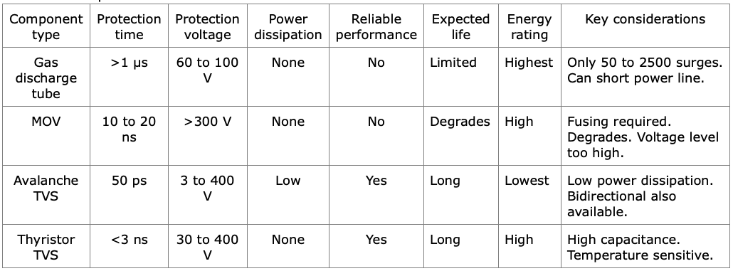
This article begins with some comments on the technology and market trends that are driving adoption of TVSs. It then provides an overview of conventional TVS devices, discussing their pros and cons, starting with historical solutions like SCRs, and then moving onto the currently used gas discharge tubes, metal oxide varistors, and TVSs. With that as background, the article describes how snapback TVS device technology offers a groundbreaking approach to circuit protection compared to previous TVS methods and devices. The characteristics and behavior of snapback TVSs are discussed with some data presented to illustrate the differences between conventional and snapback TVSs. This leads to a discussion of application benefits and an application example. The Growing Need For TVS Protection First, some history on transient voltage suppression is needed. The real world is replete with both natural and manmade transient electrical energy. In the beginning, most electronics didn't really need much protection from these events, but when electronics applications transitioned from solid-state to integrated-circuit—and now to VLSI—technologies, each generation became more sensitive to transients and surges. Circuit protection became increasingly necessary on ac and dc power lines and on the I/O connectivity that makes equipment work in the real world. Lighting applications, for example, until a short time ago were 100% electric and employed electronics based on magnetics and capacitors for their ballast designs. Then the lighting industry moved to using more complex and sensitive electronics, from high-frequency switching electronic ballasts for fluorescent lighting, to the now ubiquitous LED lighting systems that use electronic drivers. Today, proximate lightning and utility equipment switching events cause plenty of transients that can damage lighting electronics. Add to this challenge that manufacturers often require warranties of five, seven, and even 10 years—despite these electronics being more susceptible to damage. Along with the challenge of protecting more-sensitive electronic systems, electronics designers must conduct industry qualification testing and meet a number of specifications for many applications worldwide. These include IEC61000-4-2/3/4/5 and the IEEE C62.41 ringing waveform testing, as well as tests for automotive such as ISO and SAE specifications ISO7637-2 or ISO16750-2. Evolving TVS Technology Before describing snapback TVS technology, let's explore the historical approaches to mitigating electrical transients. The purpose of a TVS device is to convert transient electrical energy into transient thermal energy and to dissipate it as heat. One of its primary goals is to dissipate this heat energy as quickly as possible and then reset for another event. One of the first TVS solutions was the SCR clamp. Although it worked, this device was very prone to false triggering. Proximate noise, either conducted or radiated, entering the circuit triggered the SCR until the power source was recycled and the current through the SCR went to zero. This was not an option for equipment needing 100% uptime and, for that reason, SCR clamps aren't really used today. Another early technology, gas discharge tubes, or GDTs, were mainly used as circuit protection in the era of copper telecommunications lines to protect against lightning strikes. They are still widely used in a plethora of applications, often in combination with other protection devices. Among other benefits, GDTs are reasonably fast-responding. However, they have a limited lifetime and degrade with repeated application of transients depending on the magnitude of the transient. In the 70s, we saw the invention of the MOV (metal oxide varistor). This device was a significant step forward in TVS technology, offering many benefits and few downsides. However, both MOVs and gas tubes can fail short and thus require the addition of series current-limiting devices like fuses and circuit breakers. From the late 70s to the mid-80s, semiconductor TVS devices were developed, and were available in both bi- and uni-directional options. Semiconductor TVS device have fast response times and good thermal performance with a lifespan that can be limited by simply not overdissipating (overheating) the die too far above 175°C. They are more precise and rugged than previous methods—unless they are overdissipated. Table 1 compares the characteristics of the traditional TVS devices described above. All of these technologies have drawbacks in precision, accuracy, and temperature coefficient. For example, MOVs are not able to withstand multiple transient events. I have seen MOVs turned into talcum powder with a couple of leads sticking out of the board as a result of too much repetitive transient energy being applied. In addition, all types have a tempco issue in which the clamping voltage tends to change with temperature. It's not only the ambient temperature that's a concern in this regard but also the repetitive pulses that can heat up the protection device. This behavior is a problem since, as stated earlier, a key function of a TVS device is to dissipate the heat from the transient being converted into thermal energy.
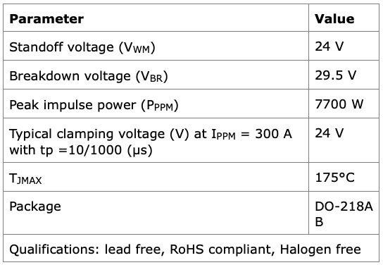
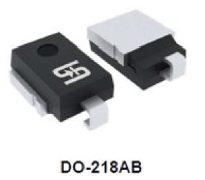
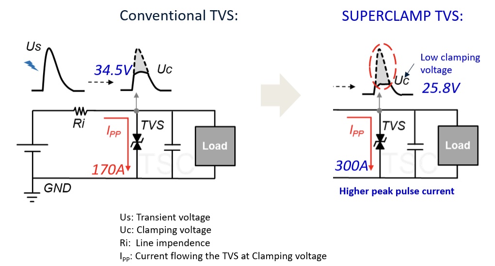
Emergence Of Snapback TVS Technology Ideally, a TVS device would have a "not to exceed" voltage, such that a 24-V bus could be protected with a 24- V protection device. It would also have zero response time, infinite ability to withstand repeated transients of any magnitude, no degradation with application of repeated transients, good reliability and long life, a high-energy rating, and the ability to fail-safe. Finally, the device would not allow applied transients to exceed the protection voltage—regardless of the device temperature. In recent years, the introduction of snapback TVS technology by semiconductor companies[1-5] has provided an evolution in transient voltage suppression that brings us closer to this ideal. Unlike traditional TVS diodes, which clamp the voltage at a certain threshold during a surge, the snapback TVS device provides a unique behavior where its clamping voltage drops to a significantly lower "snapback" level once the device begins conducting. Achieved through advanced semiconductor engineering, this capability ensures better protection for low-voltage components and minimizes the stress on the protected circuitry. And offering a much better clamping ratio than conventional TVS devices, snapback technology provides both clamping and self-resetting characteristics. In contrast, conventional TVSs act more like power Zener diodes. Snapback TVS devices, whose working principle is rooted in their silicon-based design, react almost instantaneously to transient events. This rapid response ensures that sensitive circuits are shielded from harmful voltage spikes before they can be damaged. The response time is faster than alternative options (see "Protection time" in the table above) and the ability to withstand repetitive transients is limited only by the device's die temperature—unlike MOVs and GDTs with their wearout mechanisms. Fig. 1 shows the key parameters of a Taiwan Semiconductor SUPER CLAMP device. This 7700-W, 24-V surface-mount snapback TVS device (model LTD7S24CAH)[5] offers better accuracy and precision than previous semiconductor TVS protection devices. It can pass AEC-Q automotive reliability standards even when used in extremely demanding applications. Snapback TVS technology provides powerful protection in a small form factor, making it suitable for integration into space-constrained designs. As a low-clamping TVS with snapback characteristics, the LTD7S24CAH provides an extremely low clamping ratio between working voltage (VWM) and clamping voltage (VC). The low clamping ratio TVS can suppress high surge current to provide lower clamping voltage than conventional TVS and MOV devices (Fig. 2).
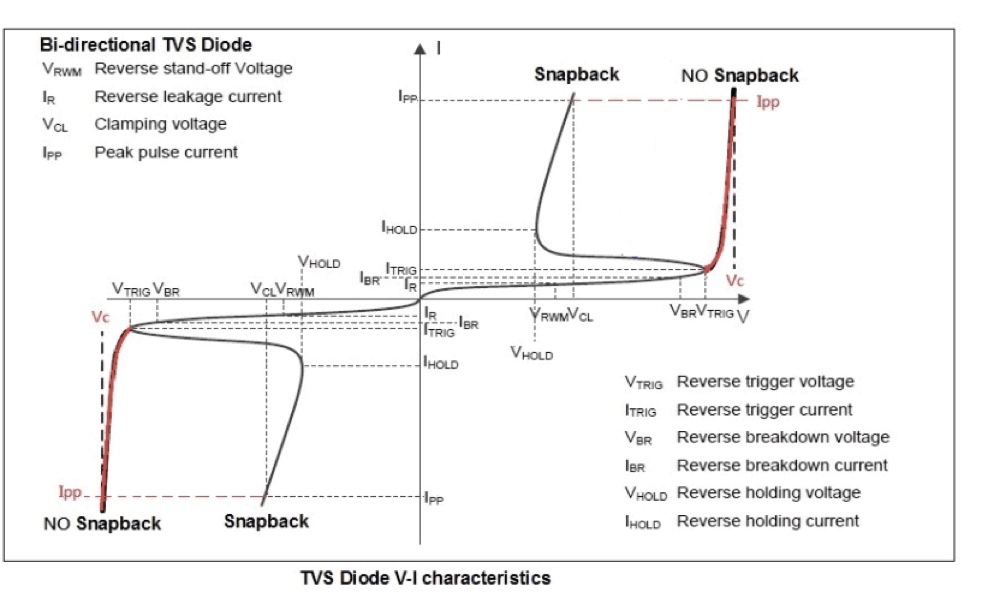
Despite their compact size, snapback TVS devices can handle substantial surge currents, offering robust protection against manmade or naturally occurring high-energy transients. Fig. 3 shows the behavior distinguishing a snapback TVS device from a conventional bidirectional TVS diode. When a transient voltage surge occurs, the device clamps the voltage to a predetermined threshold. As the current increases, the device enters a "snapback region" where the voltage decreases to a lower, more stable level to provide enhanced protection. As the current approaches zero, the snapback TVS device returns to a high impedance state, resetting for the next transient application.
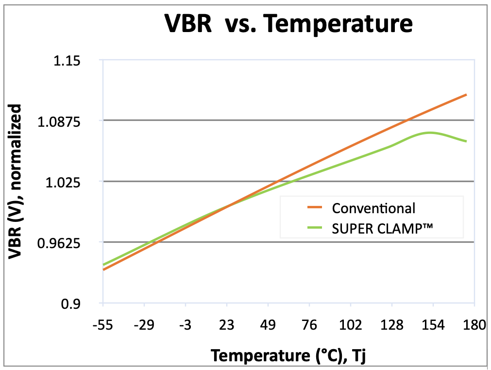
Because it has a "not to exceed" limit capability, the snapback TVS device obviates the need to overdesign. It allows designers to use lower working voltage components, such as capacitors, switching MOSFETs, reverse polarity protection diodes, and regulators. Additionally, its breakdown voltage (VBR) varies much less over temperature than conventional TVS devices (Fig. 4). This VBR stability vs. temperature helps the designer anticipate voltage range over temperature considerations (i.e., what could happen when…)
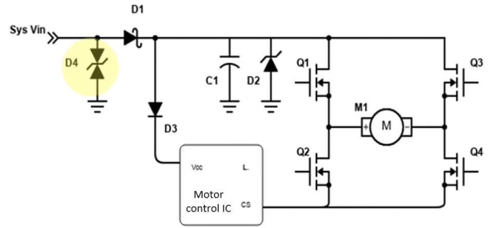
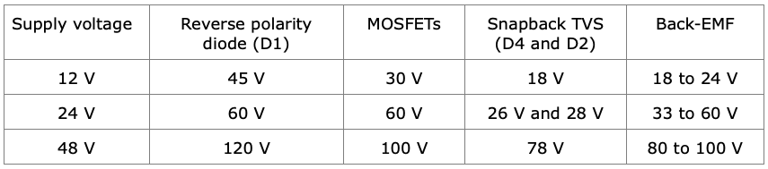
Application Benefits As electronics applications of every form continue to shrink in size, the need to meet the requirements of regulatory compliance for EMI qualification, which include transient protection, makes snapback technology a compelling approach. By reducing the voltage excursion during a surge, snapback TVS devices minimize power dissipation across the protected components, preventing damage and increasing system reliability. Eliminating the need for overdesigning, they can enhance design size and weight goals, while passing the qualification testing and increasing survivability in the application. Many electronics markets can benefit from using snapback TVS protection devices, from automotive (HEV 48-V buses, alternators) and telecom/datacom/networking and EMP protection systems, to industrial process controls, avionics, battery management systems and chargers—any protection application working at 24 V or greater. Snapback TVS technology is particularly beneficial in applications with low-voltage electronics. Its ability to return—or snap back—to a lower voltage during a surge significantly reduces the risk of overvoltage damage to downstream devices, making it very desirable for use in modern electronics that have shrinking voltage margins. The snapback TVS device can be combined with other protection methods to allow the circuit to keep working in many electrically and environmentally hostile applications. The snapback TVS technology also helps protect automotive electronics challenged by stringent reliability qualifications and cost pressures. The devices can be used in designs to help pass stringent AEC-Q testing and to survive harsh environments encountered in ICE (internal combustion engine), HEV and full electric vehicles by protecting bus voltages and the application of charging current. Additionally, snapback technology is well suited for use in industrial equipment, sensors, medical, and process automation systems that must work 24 x 7. In applications, such as factory automation equipment, that must operate reliably in harsh environments where repetitive transients are common, snapback TVS devices are not only more precise, they can also sustain multiple transient fault events and still survive, unlike MOVs and GDTs. Snapback TVS technology is also instrumental in protecting sensitive communication circuits from transients, including 5G base stations, telecom and networking systems, data transmission lines and other I/Os. Furthermore, it is essential where protection must be validated such as through UL recognition of protection devices used in the application. Additionally, snapback TVS technology allows lighting applications to meet reliability standards by surviving and continuing to operate in applications where lightning strikes and line transients are frequent occurrences. This capability is highly beneficial in a market typified by long warranties and connections to the ac mains. One caveat in the application of snapback TVSs is that there is the potential for latchup if the clamping voltage selected is below the working voltage. Application Example: BLDC Fan Speed Controller Fig. 5 illustrates how snapback TVS devices offer advantages over conventional TVS approaches when protecting a single-bridge BLDC (brushless direct current) fan speed controller. In this application example, the low VC of the snapback TVS device helps protect the motor controller and other components with lower voltage stress. Compared with using a conventional TVS or other alternatives, it also has greater power density and results in less overdesign. Table 2 lists the ratings of devices that would be applied at different supply voltages and assumes use of a snapback TVS for both D4 and D2. Consider the case described for the 24-V supply voltage. In this case the clamping voltage of the snapback TVS is just 26 V for D4, whereas in the case of a conventional TVS it would typically be 35 V.
Conclusion Its unique ability to combine low clamping voltage with robust surge-handling capacity positions the snapback TVS device as an essential component in modern electronic designs. Whether in consumer gadgets, industrial machinery or automotive systems, snapback TVS devices are set to play a crucial role in ensuring the safety and reliability of next-generation electronics of all types. As electronic devices become more sophisticated and sensitive due to VLSI geometry reductions and other low-voltage IC methods, the demand for this advanced circuit protection technology will continue to grow. Research and development in this field are likely to focus on further reducing clamping voltage, increasing surge-handling capability, and enhancing integration into multi-functional protective components. References 1. XClampR TVS, Diodes and Rectifiers - TVS Protection page, Vishay website. About The Author Kevin Parmenter is an IEEE Senior Member and has over 35 years of experience in the electronics and semiconductor industry. Kevin is currently director of Field Applications Engineering North America for Taiwan Semiconductor. Previously he was vice president of applications engineering in the U.S.A. for Excelsys, an Advanced Energy company; director of Advanced Technical Marketing for Digital Power Products at Exar; and led global product applications engineering and new product definition for Freescale Semiconductors AMPD - Analog, Mixed Signal and Power Division. Prior to that, Kevin worked for Fairchild Semiconductor in the Americas as senior director of field applications engineering and held various technical and management positions with increasing responsibility at ON Semiconductor and in the Motorola Semiconductor Products Sector. Kevin also led an applications engineering team for the start-up Primarion. Kevin serves on the board of directors of the PSMA (Power Sources Manufacturers Association) and was the general chair of APEC 2009 (the IEEE Applied Power Electronics Conference.) Kevin has also had design engineering experience in the medical electronics and military electronics fields. He holds a BSEE from Purdue University and a BS in Business Administration from Colorado Technical University, is a member of the IEEE, and holds an Amateur Extra class FCC license (call sign KG5Q) as well as an FCC Commercial Radiotelephone License. For further reading on circuit protection in power electronics, see the "How2Power Design Guide," locate the Design area category and select "Power Protection".
This article originally appeared in the February issue of How2Power Today, available online at www.how2power.com/newsletters.
|
|||||||||||||||||||||||||||||||||||||||
| <<-Contents | <-Previous | Page 6 | Next-> | |||||||||||||||||||||||||||||||||||||||
|
If you or anyone in your company is interested in getting on the distribution list for future issues of PSMA UPDATE, please send e-mail to: power@psma.com. Be sure to include your name and
|
|||||||||||||||||||||||||||||||||||||||